



What Are Precision Mold Components?

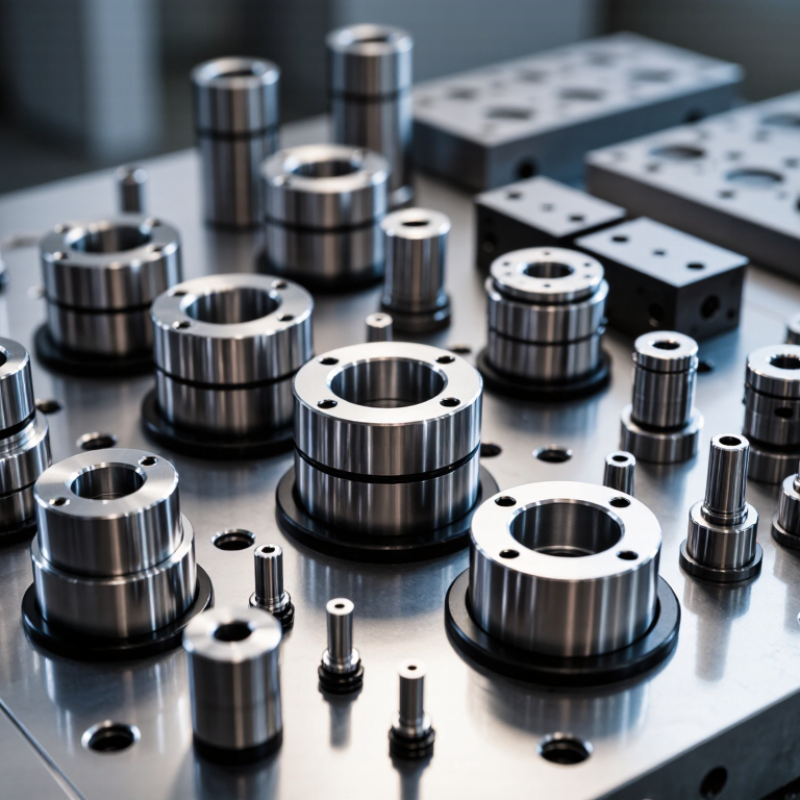
Precision Mold Components are the small, engineered parts that help a mold form plastic or metal products accurately and repeatedly. They include cores, cavities, inserts, ejector pins, guide pins, and bushings. Each has a specific job. A cavity shapes the outer surface; an ejector pin helps release the finished part. Even a tiny mismatch can leave flash, cause sticking, or shift dimensions.

Their value is easiest to see on the shop floor. Imagine a polished cavity insert meeting a guide pin during thousands of cycles. If alignment drifts, the wear may show as a fine line on molded parts. Small details matter. Quality authority Joseph M. Juran defined quality as “fitness for use,” a useful standard for assessing these components. A part is not precise merely because its drawing has tight tolerances. It must also fit the mold, withstand operating conditions, and perform consistently in production.

This introduction explains what Precision Mold Components are, how their functions differ, and which factors shape their accuracy and service life. Material choice, heat treatment, surface finish, and dimensional inspection all deserve attention. Yet specifications alone cannot tell the whole story. Real production conditions expose weaknesses that a drawing may miss. That point is easy to underestimate.
What Are Precision Mold Components?

Definition and Role of Precision Mold Components

Precision mold components are the fitted parts that shape, guide, cool, and release a molded product. They are not the mold by themselves. They work together inside the mold assembly. Common examples include cores, cavities, guide pins, bushings, ejector pins, and cooling inserts. The cavity forms the part’s outer surfaces. The core creates internal features, such as holes or channels. Small dimensional differences can affect fit, surface finish, and repeatability.

Their role is to keep each molding cycle controlled. Guide pins help the mold halves meet in the correct position. Ejector pins push the finished part free without excessive distortion. Cooling channels remove heat, helping the part solidify more evenly. In practice, a poorly matched pin or uneven cooling can leave flash, drag marks, or warping. Component selection depends on the material, expected production volume, and part geometry. A drawing may specify dimensions, but it cannot always show how a feature will wear over time. That deserves a second look.

Tips: Check clearances, wear surfaces, and cooling access during design review. Not every area needs extreme precision; tighter tolerances can add cost without improving the part.

Key Components and Their Functions

What Are Precision Mold Components?
Key Components and Their Functions

Precision mold components work together to shape plastic parts repeatedly, often within tight dimensional limits. The cavity forms the part’s outer surfaces, while the core creates internal features such as holes or ribs. Their alignment matters. Even slight mismatch can leave a visible step or uneven wall thickness. Inserts handle local details, including threads, sharp corners, or wear-prone areas, and can be replaced without rebuilding the whole mold.

Guide pins and bushings bring the two mold halves into position during closing. Ejector pins then push the cooled part free; poor placement may leave marks or bend a thin feature. Small parts matter. Cooling channels carry water through the mold to control temperature and cycle time. Uneven cooling can cause warping, even when the cavity dimensions are correct. The sprue, runners, and gate guide molten plastic into the cavity, so their size and location affect filling and surface quality. In practice, these features require adjustment for the chosen resin and part geometry. A setup that looks sound on a drawing may still need careful testing. Maintenance also counts: residue, wear, or a damaged pin can quietly reduce consistency.

What Are Precision Mold Components? — Key Components and Their Functions

Typical hardness ranges for selected injection-mold components, shown in Rockwell C (HRC).

  • Mold base: Supports the mold assembly and keeps its plates aligned.
  • Cavity and core inserts: Form the part’s exterior and interior surfaces.
  • Ejector pins: Push the molded part out after cooling.
  • Guide pins and bushings: Align the mold halves during opening and closing.
  • Sprue bushing: Guides molten plastic from the machine nozzle into the mold.

Hardness ranges are typical examples, not universal specifications; actual values depend on material grade, heat treatment, and application.

Materials and Manufacturing Processes

Precision mold components are made from materials chosen for heat, pressure, wear, and corrosion—not just hardness. Tool steels suit cavity inserts and cores that face repeated cycles; stainless steels help where moisture or corrosive resins are concerns. Copper alloys can move heat quickly around hot spots, while aluminum is useful for lighter, lower-volume tooling. ISO 4957:2018 groups tool steels into cold-work, hot-work, high-speed, and other alloy tool steels. That classification helps narrow choices, but it does not replace checking the actual operating conditions. A material can look right on paper and still wear too quickly in service.

Manufacturing usually combines CNC milling, turning, heat treatment, electrical discharge machining, and finish grinding. EDM can form narrow ribs and deep slots that a cutting tool cannot reach cleanly. Heat treatment may distort a part, so finish stock and inspection plans matter. ISO 286-1:2010 defines 20 tolerance grades, from IT01 to IT18, giving engineers a shared framework for specifying fits. Yet a tolerance grade alone does not guarantee a good mold: measurement temperature, part geometry, and setup can all shift the result. Small errors matter. A few microns at a shutoff edge can leave flash, while an overly tight fit may bind after heating. There is no perfect shortcut here; material and process choices still need to be tested against real production conditions.

What Are Precision Mold Components? - Materials and Manufacturing Processes

Component Purpose Common Materials Typical Manufacturing Processes Key Design and Quality Considerations
Cavity and core inserts Form the exterior and interior surfaces of a molded part. Pre-hardened mold steel; hardened hot-work tool steel; corrosion-resistant mold steel for moisture-sensitive or corrosive environments. CNC milling, turning where applicable, heat treatment, surface grinding, electrical discharge machining (EDM), and polishing or texturing. Dimensional accuracy, surface finish, wear resistance, and cooling layout affect part quality and cycle time. Steel selection depends on resin, production volume, and corrosion or abrasion exposure.
Mold base plates Support and align the mold assembly and provide mounting surfaces for its components. Pre-hardened low-alloy steel; medium-carbon steel for plates requiring additional strength or hardening. Cutting, CNC milling, drilling, tapping, and surface grinding; heat treatment may be used where required by the design. Flatness, parallelism, alignment, and adequate stiffness help maintain reliable mold operation under clamping force.
Ejector pins Push the molded part off the core during ejection. Hardened tool steel, commonly hot-work or high-speed tool steel, selected for wear and temperature requirements. Precision turning or grinding, heat treatment, and finish grinding of the working diameter and end. Pin clearance and straightness must suit the mold and resin. Incorrect fit can contribute to flash, pin binding, or visible marks on the part.
Guide pins and guide bushings Align the two mold halves as they close. Hardened alloy or bearing-grade steel; bushings may use hardened steel or other wear-resistant materials. Turning, heat treatment, cylindrical grinding, and precision boring or honing of bushings. Running clearance, coaxiality, lubrication, and wear resistance help prevent misalignment and damage to the mold faces.
Slides and lifters Form side features or undercuts that cannot be released by straight mold opening alone. Pre-hardened or hardened alloy tool steel; wear plates or inserts may use harder, wear-resistant steel. CNC milling, grinding, EDM for intricate features, heat treatment, and fitting of mating surfaces. Sliding clearances, contact area, guidance, and wear surfaces must be designed for the required travel and molding loads.
Sprue bushing Connect the molding machine nozzle to the mold’s runner system. Hardened tool steel or other heat- and wear-resistant steel. Turning, drilling, heat treatment, grinding, and polishing of the sprue passage and nozzle seating area. Entry geometry and nozzle contact must match the molding setup. A smooth, correctly sized passage supports consistent melt flow and sprue release.
Cooling-channel components Carry coolant through or around the mold to control temperature and remove heat. Mold steel; corrosion-resistant steel or compatible fittings may be selected for the coolant and operating environment. Drilling, deep-hole drilling, milling, sealing, and pressure or leak testing; conformal channels may be produced by metal additive manufacturing. Channel placement, flow, sealing, and corrosion control affect temperature uniformity and cycle time. The design must avoid weakening critical mold sections.

Material and process choices vary with the molded resin, part geometry, production volume, operating conditions, and required service life.

Precision Standards and Quality Inspection

Precision mold components depend on controlled dimensions, repeatable fits, and clear inspection criteria. ISO 286-2:2010 gives a 15 μm tolerance band for a 10 mm H7 hole. That small allowance can determine whether a core pin slides smoothly or binds after assembly. Fit is unforgiving.

Inspection should connect the drawing to the real part. A coordinate measuring machine can check cavity positions and flatness; calibrated pin gauges can verify small bores. Record measured values, not only pass-or-fail marks. Burrs, coolant residue, and temperature changes can distort readings, especially on small features. Clean the part and stabilize its temperature before measurement. These steps sound ordinary. They prevent avoidable disputes.

A useful inspection plan identifies critical dimensions, measurement methods, instrument resolution, and sampling frequency. Keep calibration records and note uncertainty when measurements sit close to tolerance limits. This follows the measurement-traceability principles described in the NIST/SEMATECH e-Handbook of Statistical Methods. A first-article check can reveal machining drift, while periodic checks catch wear in punches and cavities. Still, a perfect report cannot explain every poor fit. The fixture, operator technique, or assembly conditions may deserve another look.

Applications, Maintenance, and Service Life

Precision mold components guide how a mold opens, closes, aligns, and releases a part. They include guide pins, bushings, ejector pins, slides, and replaceable inserts. These parts are used in plastic injection, die-casting, and other molding processes. Their dimensions and fit affect part consistency, cycle time, and the risk of flash or sticking. Small differences matter.

Maintenance should follow the component’s role and the mold’s operating conditions. After a production run, remove residue with a suitable, non-abrasive method. Check pins and bushings for scoring, discoloration, or uneven wear. Inspect ejectors for bending and confirm that slides move smoothly. Apply the lubricant specified for the mold and process; excess grease can attract debris. Keep inspection notes. A simple record of cycles, repairs, and measurements can reveal gradual wear before it causes repeated defects.

Service life varies. Resin, pressure, temperature, cooling, alignment, and cleaning practices all influence wear. A component may last through many production runs, but cycle count alone cannot confirm its condition. Replace parts when measurements exceed the drawing tolerance or when damage affects movement or part quality. Matching replacement dimensions is essential. It is easy to overlook alignment after a repair, and that can shorten the life of nearby components. Check the assembled mold under controlled conditions before returning it to full production.

Whether your solution requires a single pumping application or an expansive engineered system,
CheckPoint is committed to becoming your partner in excellence.